Nozzle Capacity

What is the nozzle capacity?

There are nozzles of different shapes and sizes. An important parameter for choosing the right nozzle for your appliance is the nozzle size. Generally speaking, a larger nozzle experiencing higher pressure has a higher flow capacity of liquid or gaseous fluid than a smaller nozzle. However, the design of the nozzle also has an impact on the flow capacity at a certain pressure.
Additionally, the design has a great impact of the shape of the spray. The adjacent figure shows a few examples of nozzle shapes using the example of a sprinkler head used for cleaning. A hole type nozzle creates a full jet, while a slot type is often used in flat fan nozzles. A hollow cone nozzle shows the characteristic spray pattern with the tip of the cone facing the approaching flow. The unique design of the OsciJet nozzles creates an oscillating or pulsing jet.
In order to achieve comparability between nozzles of different designs, the nozzle size is not defined by the dimensions of the nozzle, but rather through the volumetric flow rate regarding a reference pressure. The FDX product line uses the common definition:


\(\mathsf{ \textsf{nozzle capacity } \widehat{=} \textsf{ volumetric flow rate in (l/min)} \cdot 10 \textsf{ at } 20 \textsf{ bar} }\)

Which is equivalent to:


\(\mathsf{ \textsf{nozzle capacity } \widehat{=} \textsf{ volumetric flow rate in (US liq. gal/min)} \cdot 2.6417 \textsf{ at } 290 \textsf{ psi} }\)

In fluid mechanics, the flow coefficient, which indicates the volumetric flow rate at a reference pressure of 1 bar (Kv) , is more commonly used whereas the definition using 20 bar as a reference pressure predominates the industry.

Nozzle Capacity. Volumetric Flow Rate. Units.

To spare you the cumbersome calculations by hand and to juggle with units, we have created an interactive nozzle capacity calculator which you can find on our product pages. The calculator also helps you finding the right nozzle and you can also save the nozzle characteristic for the use in other programs. Please feel free to contact our sales team for support. They are happy to help.

How do I choose the right nozzle capacity?

Using the following formula, knowing the volumetric flow rate for a single pressure suffices to determine the nozzle capacity C:

\( \mathsf{ C = \frac{10\cdot \textsf{V (l/min)}}{ \sqrt{ \frac{ \textsf{p (bar)} }{20} } } } \)

For example is the volumetric flow rate for a nozzle with the capacity of C=100 at 20 bar or 290 psi 10 liters per minute or 2.6417 US liq. gallons.

How do pressure, flow capacity and design relate?

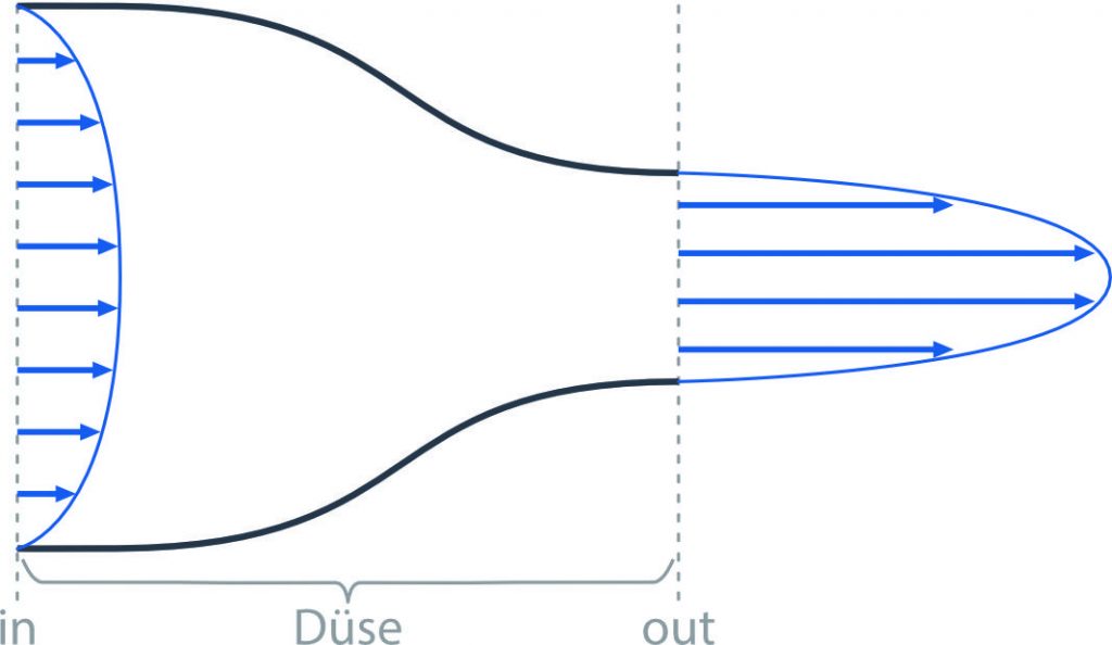
The goal shall be to characterize the current through the nozzle based on the variables pressure p, mass flow rate \(\mathsf{\dot{m}}\) and cross-sectional area A. Using two of the conservation equations of fluid mechanics:

  1. the conservation of mass, and
  2. the conservation of energy

between two point of the current, the inlet (in) and outlet (out)) of the nozzle, leads to the following formulas:

\( \begin{align} \mathsf{ \varrho_{in} \cdot A_{in} \cdot u_{in} } & = \mathsf{ \varrho_{out} \cdot A_{out} \cdot u_{out} = \dot{m}} \tag{1} \\ \mathsf{ p_{in} + \frac{1}{2} \varrho_{in} \cdot u_{in}^2 + \varrho_{in} \cdot g \cdot h } & = \mathsf{ p_{out} + \frac{1}{2} \varrho_{out} \cdot u_{out}^2 + \varrho_{out}\cdot g \cdot h + \Delta p_v }\tag{2} \end{align}\)

Formula (1) states that the mass flow rate \(\mathsf{\dot{m}}\) remains constant downstream. Formula (2) is known as Bernoulli’s principle and describes the conversion of mechanical energy resulting from pressure, kinetic energy and potential energy along the filament of flow. Occurring energy loss dissipates into thermal energy and is represented in the factor \(\mathsf{\Delta p_v}\). Other unknown variables in formulas (1) and (2) are the mass density \(\mathsf{\varrho}\), the velocity \(\mathsf{u}\) and the geodetic height \(\mathsf{h}\). The gravitational acceleration \(\mathsf{g}\) shall be approximated through through \(\mathsf{g\approx 9,81 \frac{m}{s^2}}\).

Both Formulas already include simplifications applied to the Navier-Stokes equations. The Navier-Stokes equations are capable of describing these current behaviors including turbulent phenomena completely, however it can only be solved with numerical approximations due to its complexity. Therefore, Bernoulli’s principle shall hence be used and further simplified:

  • due to only small changes in the geodetic height potential energy will be disregarded
  • the conversion of mechanical energy resulting from pressure into kinetic energy shall be without loss (\(\mathsf{\Delta p_v=0}\))
  • the fluid shall be incompressible, e.q. water (\(\mathsf{\varrho_{in} = \varrho_{out} }\))
  • pressure differences over the nozzle shall be summarized in \(\mathsf{\Delta p}\) (in general the pressure at the outlet is equal to the ambient pressure
  • the average velocity at the outlet is a great deal larger than the one at the inlet (\(\mathsf{u_{out} – u_{in} \approx u_{out} }\))

With the assumptions above the formulas can be simplified:

\( \begin{align} \mathsf{ \dot{m} } & = \mathsf{ \varrho \cdot A_{out} \cdot u_{out} } \tag{1} \\ \mathsf{ \Delta p } & = \mathsf{ \frac{1}{2} \varrho \cdot u_{out}^2 }\tag{2} \end{align}\)

Combining both formulas results in the following:

\( \begin{align} \mathsf{ \dot{m}} &= \mathsf{A_{out} \cdot \sqrt{2 \varrho \cdot \Delta p } } \end{align} \)

This formula provides us with a simple interrelation of material throughput, loss of pressure and cross-sectional area of the current. It also provides the formula for the nozzle capacity C. A comparison with measured data shows a very good agreement. We can hence devise the following relations between the variables:

  • A linear relation connects the material throughput to the cross-sectional area, i.e. a doubling of the cross-sectional area will result in a doubling of the material throughput regarding a constant pressure.
  • The volumetric flow rate is connected to the pressure by a root relation. A quadruplication of the pressure will lead to a doubling in flow capacity.

Schematic of a nozzle with velocity profiles at the inlet (in) and outlet (out).

How efficient is the nozzle?

Efficiency regarding a nozzle can be interpreted as the percentage of pressure energy built up upstream of the nozzle that is converted into kinetic energy. The less dissipative this process, the higher the flow capacity of the nozzle at a fixed pressure. The maximum in achievable mass flow rate \(\mathsf{\dot{m}_{th} }\) can be calculated with the established formula:

\( \mathsf{ \dot{m}_{th} = A_{out}\cdot \sqrt{2\varrho\cdot\Delta p} } \)

In reality, conversion of energy is a process afflicted with loss of energy, mainly caused by friction within the current and along the boundary surfaces of the walls, leading to a smaller material throughput. A measure for efficiency is the discharge coefficient \(\mathsf{C_{d} }\) of a nozzle,

\( \mathsf{ C_d = \frac{\dot{m}}{\dot{m}_{th}} = \frac{A_{out}}{A_{out,th}} } \)

It indicates the ratio of actual to theoretically possible material throughput and normally reaches value between 0.6 and 0.9. A higher ratio directly adds up to a higher efficiency.

How do I calculate the geometrical size of the nozzle?

Due to the linear relation of volumetric flow rate to cross-sectional area, the geometrical size of the nozzle can be calculated, provided that the discharge coefficient, pressure and respective volumetric flow rate are known:

\( \mathsf{ A_{geo} = \frac{C_d \cdot \dot{m}}{\sqrt{2\varrho\Delta p}} } \)

Commonly, an equivalent hole diameter is stated to enable the comparison of the cross sections of two nozzles independently of their design.

Cookie Consent with Real Cookie Banner